Placer County ARES (Page)

PLACER COUNTY ARES HAS A NEW WEBSITE

CLICK HERE

The Placer County Amateur Radio Emergency Service (ARES) consists of licensed amateurs who have voluntarily registered their qualifications and equipment for communications duty in the public service when disaster strikes.

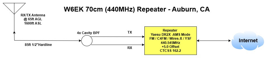
The Placer County ARES net is on the 3rd Sunday of the month, starting at 1930 (7:30 PM) PT on the W6EK 2M Repeater.

Everyone is invited to check-in. You do not need to be an SFARC member to participate.

Groups.io (Page)

WHAT IS GROUPS.IO?

Groups.io provides an expansive set of web-based group communication tools, including a calendar, wiki, files, and a forum for chatting.

SFARC uses Groups.io to collaborate, post items for sale, share stories, and work on ham-related projects.
Click here to login to Groups.io

Connect With SFARC (Page)

There are many ways to connect with the Sierra Foothills Amateur Radio Club.

Join the FRIENDS OF SFARC mailing list.  This allows you to keep track of what the club is doing and decide whether or not you want to become a member.  The vast majority of events hosted by SFARC are open to all.  CLICK HERE to enroll.

CLUB MEETING is a great place to interact with us, meet friends or make new ones, learn about other activities, and ask questions 1-on-1.

Like or follow SFARC on one of the five major SOCIAL MEDIA platforms. You don’t have to “be on Facebook” to take part. We’re VERY active on Instagram, Twitter, LinkedIn, and YouTube.

Collaborate with SFARC on GROUPS.IO.  SFARC uses Groups.io to collaborate, post items for sale, share stories, and ham-related projects.

Join a club meeting on ZOOM.  Can’t make it to one of our meetings in person? No problem!  SFARC provides a robust and interactive experience for all club meetings.

Join us at a CLUB EVENT OR ACTIVITY.  You don’t need to be a member to join us for the numerous events and activities we take part in.  Don’t be a stranger, come and say hi.

ARRL (Page)

WHAT IS THE ARRL?

The ARRL, the National Association for Amateur Radio (ARRL) is the national association for amateur radio (ham radio) operators in the United States, founded in 1914. The ARRL recognizes SFARC as a special service club for our commitment to the local community and emergency

Small ARRL LogoIts main roles include:

  • Advocacy & representation for amateur radio with the FCC and international regulators
  • Education & licensing support, including study materials and exams
  • Operating activities like contests, awards, and emergency communications programs
  • Publications, most notably QST magazine
  • Emergency communications, coordinating volunteer hams during disasters via ARES (Amateur Radio Emergency Service)

From The Desk of the ARRL

09/16/2026Contest University Celebrates 100 Years of YagisThe Yagi-Uda beam antenna was invented 100 years ago, in 1926, and Contest University (CTU) is celebrating its centennial with a live Zoom webinar this Saturday, September 19, 2026, at 1600 UTC (noon Eastern). The free webinar, titled “The Yagi Turns 100,” will be available online at https://w3lif.o… READ MORE
09/14/2026The ARRL Solar UpdateSolar flare activity was at low levels in the past week withisolated C-class flare activity, according to NOAA’s Space WeatherPrediction Center. The largest flare of the period was a C3.4 onSeptember 8 from otherwise stable Region 4528. Region 4530 developedasymmetric penumbra on both its leading an… READ MORE
09/11/2026Special HAARP Transmission for 9/11To commemorate the 25th anniversary of the September 11, 2001 attacks on the United States, the High-frequency Active Auroral Research Program (HAARP) at the University of Alaska Fairbanks will be making a special transmission on 9.11 MHz at 0030-0035 UTC on September 12, 2026 (8:30-8:35 PM eastern… READ MORE
09/11/2026Video: Educator Shows How Amateur Radio Is Inspiring StudentsEducator Everton Henriques, KD2ZZT, shared his experience using amateur radio to inspire students and bring engineering and technology to life in the classroom during his keynote at the 2026 ARRL New England Division Convention, hosted by Northeast HamXposition in Massachusetts on August 15. A video… READ MORE
09/11/2026Answering the Call: A 9/11 Remembrance from ARRLEd. Note: Details in this article were culled from the November 2001 QST article, “9/11/01: ‘This is Not a Test’ ” by Rick Lindquist, N1RL, and Diane Ortiz, K2DO. The original article is available here (PDF).Twenty-five years ago, on September 11, 2001, the United States came under attack from al-Qa… READ MORE

Check out all the ARRL has to offer by visiting their website @ https://www.arrl.org/ Continue reading ARRL (Page)

Interactive Band Plan (Tile)

INTERACTIVE BAND PLAN

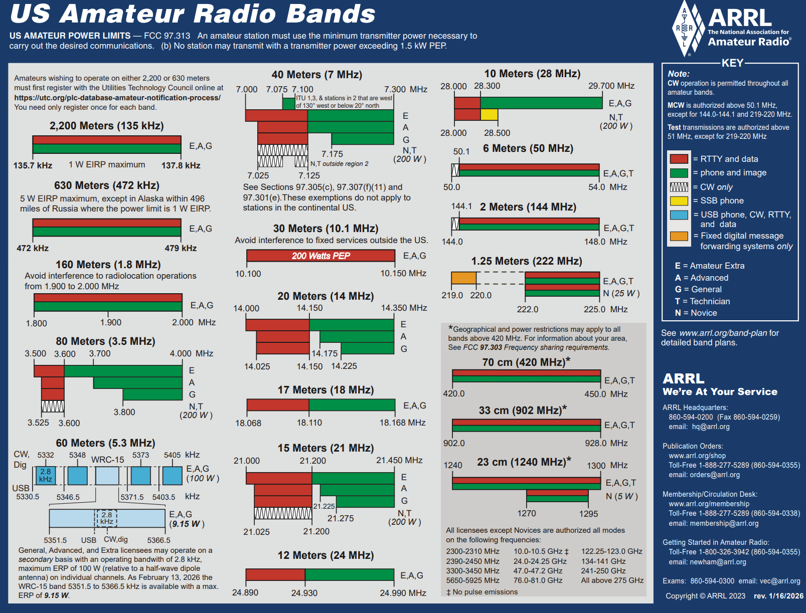
The ARRL band plan is a PDF you squint at, scroll through, and eventually give up on. The following is the same information made usable and interactive.

Search a frequency or a mode and jump straight to it. Filter by license class to see exactly where your privileges begin and end. Every segment is color-coded by mode, so you can tell at a glance whether you’re about to call CQ in the middle of the digital watering hole.

Covers 2200 meters through microwave. Works on your phone in the field, on your laptop at the operating desk, and in color-blind-friendly and light modes.

A band plan is a voluntary agreement among operators to keep incompatible modes out of each other’s way. It is not the law, Part 97 is. Always check current FCC rules before transmitting.

SFARC SPECTRUM EXPLORER

A band plan is a voluntary division of a band to avoid interference between incompatible modes.

Where can I operate?
  • CW
  • Phone / SSB / AM
  • Digital / Data
  • FM / Repeater
  • Beacons
  • Satellite / EME
  • ATV / SSTV
  • Experimental
  • Other / Shared
Based on the ARRL Band Plan. Locally coordinated plans always take precedence.

DOWNLOAD

What is Five Nine? (Tile)

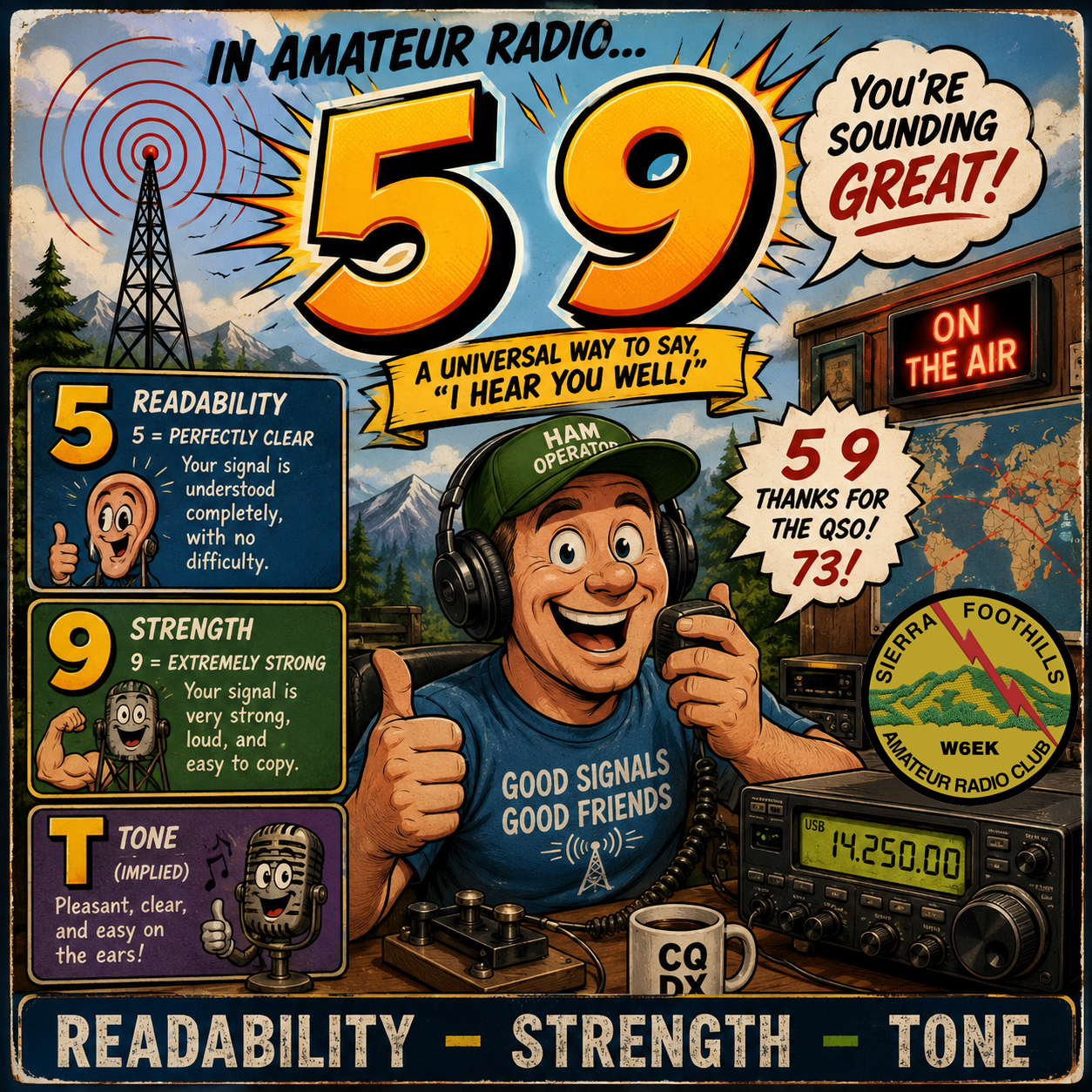
WHAT IS FIVE NINE (5 9) AND WHAT DOES IT MEAN?

The R-S-T system is used by amateur radio operators, shortwave listeners, and other radio hobbyists to exchange information about the quality of a radio signal being received. The code is a three-digit number, with one digit each for conveying an assessment of the signal’s readability, strength, and tone. The code was developed in 1934 by amateur radio operator Arthur W. Braaten, W2BSR.
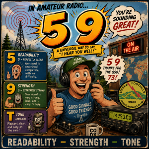
The R stands for “Readability“. Readability is a qualitative assessment of how easy or difficult it is to correctly copy the information being sent during the transmission. In a Morse code telegraphy transmission, readability refers to how easy or difficult it is to distinguish each of the characters in the text of the message being sent; in a voice transmission, readability refers to how easy or difficult it is for each spoken word to be understood correctly. “Readability” is measured on a scale of 1 to 5.

The S stands for “Strength“. Strength is an assessment of how powerful the received signal is at the receiving location. Although an accurate signal strength meter can determine a quantitative value for signal strength, in practice, this portion of the RST code is a qualitative assessment, often made based on the S meter of the radio receiver at the location of signal reception. “Strength” is measured on a scale of 1 to 9.

The T stands for “Tone” and is measured on a scale of 1 to 9. Tone only pertains to Morse code and other digital transmission modes and is therefore omitted during voice operations. With modern technology, imperfections in the quality of transmitters’ digital modulation severe enough to be detected by human ears are rare.

Readability

Strength

5. Perfectly readable

9. Extremely strong signals

4. Readable with practically no difficulty

8. Strong signals

3. Readable with considerable difficulty

7. Moderately strong signals

2. Barely readable, occasional words distinguishable

6. Good signals

1. Unreadable

5. Fairly good signals

4. Fair signals

3. Weak signals

2. Very weak signals

1. Faint—signals barely perceptible

Understanding RFI (Tile)

Understanding RFI

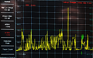
RFI happens when electromagnetic signals from one device disrupt the normal operation of another. These signals can be intentional (like a radio transmitter) or accidental (like electrical noise).

Common Sources Include:
– Cell Phones & Wi-Fi Routers
– Power Lines & Electrical Motors
– LED Lights & Switching Power Supplies
– Computers, Monitors, USB cables
– Vehicle Ignition Systems
– Radio/TV Transmitters
– EV Car Chargers
– Solar Inverters

Interference occurs when unwanted radio-frequency signals disrupt the use of your television, radio, or cordless telephone. Interference may prevent reception altogether, cause only a temporary loss of signal, or affect the quality of the sound or picture produced by your equipment.
How Can I Reduce It?
– Shielding (metal enclosures, braided cables)
– Filtering (ferrite beads, line filters)
– Better grounding
– Physical separation between noisy and sensitive devices
– Good cable routing and design

Sometimes you can take all of the above steps and STILL have RFI issues.  When in doubt, check out additional resources from the American Radio Relay League or file a report with the Federal Communications Commission (FCC).

22 Things You Can Do With Ham Radio (Tile)

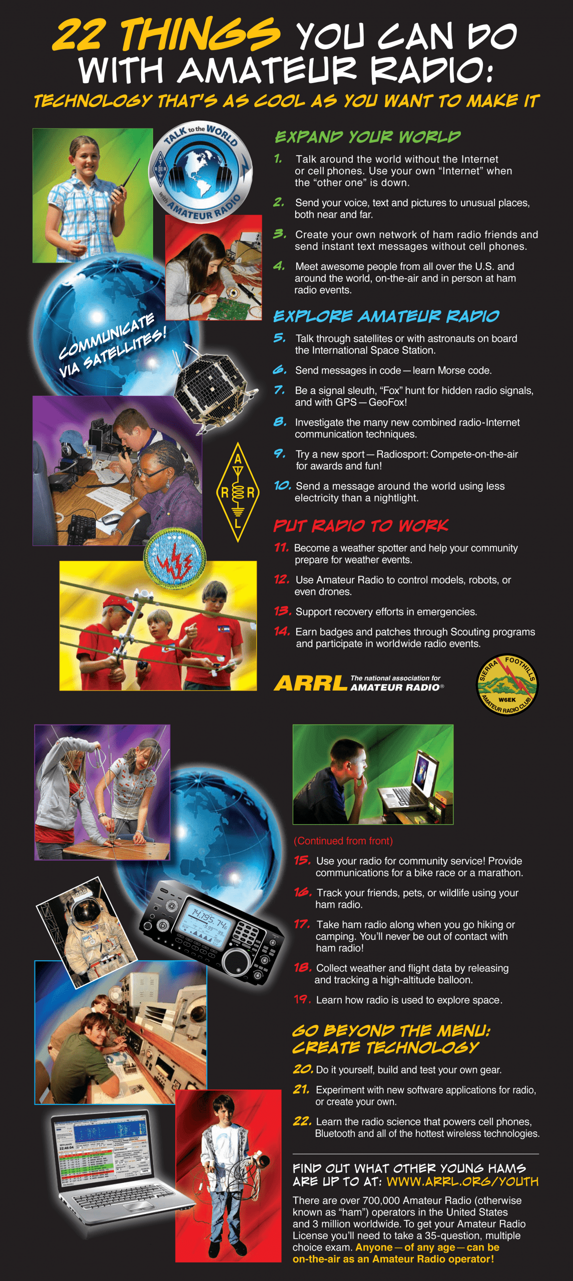
22 Things You Can Do With Ham Radio

Somewhere above your head, right now, there’s a satellite you could talk through. There’s a balloon sending back weather data. There’s a stranger in Japan who’d be delighted to hear from you.

Amateur radio — ham radio — is the hobby that gets you there. You build the gear, you make the contact, you keep talking when the internet quits. No subscription, no algorithm, no waiting for permission. Just you, an antenna, and everything the sky will carry.

Here are 22 places to start.

All About Connectors (Tile)

ALL ABOUT CONNECTORS

Choosing the right RF connector matters more than it looks. The wrong choice can add loss, raise SWR, let water into your feedline, or simply fail to mate with your gear. This guide compares two of the most common coaxial connectors in amateur and commercial radio — the PL-259 (UHF) and the N Type — and then summarises the other connectors you are most likely to meet: SMA, SMB, MMCX, MCX, TNC and BNC.

PL-259 vs. N Type at a glance

Property PL-259 (UHF) N Type
Coupling Threaded (5/8″-24) Threaded (5/8″-24), precision interface
Impedance Not a true constant-impedance design (nominally 50Ω) Constant 50Ω (75Ω version also made)
Practical frequency range HF/VHF, generally to ~300 MHz DC to 11 GHz (precision versions to 18 GHz)
Weatherproofing Not weatherproof on its own Weatherproof when correctly mated (gasket/O-ring)
Power handling High at HF/VHF; robust body High, with better consistency at UHF and above
Cost & assembly Cheap, easy to solder, very forgiving Dearer, more parts, needs careful assembly
Typical use HF/VHF ham rigs, CB, antenna tuners UHF/microwave antennas, Wi-Fi, cellular, test gear

PL-259 (the “UHF” connector)

Despite the name, the PL-259 is best thought of as an HF and VHF connector. It dates from the 1930s, when “UHF” meant anything above about 30 MHz. The plug is the PL-259 and the matching socket is the SO-239 (the “PL” and “SO” come from old Signal Corps nomenclature for plug and socket).

It is not a true constant-impedance connector — there is a noticeable impedance discontinuity through the joint — so performance falls away as you climb in frequency. Its strengths are that it is inexpensive, mechanically tough, easy to solder onto thick coax like RG-8 or RG-213, and almost universal on HF and VHF amateur equipment.

Rule of thumb: fine to about 300 MHz; above that, expect rising SWR and use something better.

N Type

The N Type was developed at Bell Labs in the 1940s by Paul Neill (the “N” is for Neill). Unlike the PL-259 it is a genuine 50Ω constant-impedance connector, which makes it well behaved all the way up to 11 GHz, and to 18 GHz in precision versions. Properly mated it is weatherproof, which is why it is the default choice for mast-mounted antennas, Wi-Fi and cellular systems, and microwave links.

The trade-offs are cost, a few more parts to assemble, and the need for more care during termination.

Careful: a 75Ω variant exists for broadcast and CATV work. 50Ω and 75Ω N connectors should not be mated — the differing pin diameters can damage them.

Which should I use?

For HF and VHF on a budget, or to match existing ham gear, the PL-259 is hard to beat. For anything outdoors, anything above ~300 MHz, or where low loss and a clean match matter, choose N Type.

Other common RF connectors

Beyond these two, a handful of smaller connectors turn up constantly in modern radios, antennas, modules and test equipment. The table below summarises the essentials; brief notes follow.

Connector Coupling Impedance Typical max frequency Where you’ll see it
BNC Bayonet (quarter-turn) 50Ω & 75Ω ~4 GHz (50Ω) Test gear, oscilloscopes, video/SDI, older networking
TNC Threaded 50Ω (75Ω made) ~11 GHz Threaded “BNC” for vibration/microwave environments
SMA Threaded (1/4″-36) 50Ω (75Ω rare) 18 GHz (to 26.5 GHz) Wi-Fi, GPS, handheld antennas, RF modules, test gear
SMB Snap-on (push) 50Ω & 75Ω ~4 GHz Tight spaces needing quick, repeated connections
MCX Snap-on (push) 50Ω (75Ω made) ~6 GHz GPS, cellular, compact devices (~30% smaller than SMB)
MMCX Snap-on (push) 50Ω ~6 GHz Wi-Fi/M.2 cards, tiny antennas, IEMs — smaller than MCX

Quick notes

BNC
A fast bayonet lock that is the workhorse of the test bench. The 50Ω type is for RF; the 75Ω type for video. Convenient but not for high microwave frequencies.
TNC
Essentially a threaded BNC. The screw coupling makes it far more reliable under vibration and pushes the usable range up to around 11 GHz.
SMA
The small threaded connector you find on most Wi-Fi and GPS antennas and on countless RF modules. Excellent to 18 GHz, but the threads have a limited number of mating cycles, so don’t treat it as a frequent connect/disconnect joint. Watch out for RP-SMA (reverse-polarity), which is common on consumer Wi-Fi gear and will not mate with standard SMA.
SMB
A push-on snap fit that is quicker than SMA in cramped assemblies, at the cost of a lower frequency ceiling.
MCX / MMCX
Progressively smaller snap-on connectors for space-constrained devices such as GPS modules, laptop wireless cards and compact antennas. MMCX adds a little rotational freedom, handy for routing thin cables.

A note on the names: several of these share a heritage. N is for Neill, BNC is Bayonet Neill–Concelman, and TNC is Threaded Neill–Concelman — so the B and T simply tell you how the connector locks.

0 Item | $0.00
View Cart
MENU