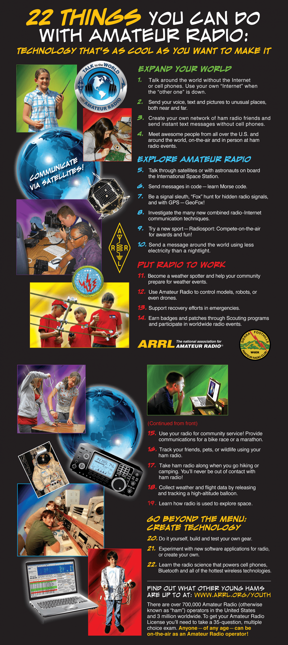
CALIFORNIA STATE FAIR SPECIAL STATION, MY EXPERIENCE
by John Moorhead (KE6JEM)
I’m what I refer to as a “new-old ham”, having been licensed originally in 1968 for a few years, but then I had to give it up due to intense college studies and later work commitments. I set a bucket list item last year in my retirement and re-gained my license on Christmas Day and received my vanity call a few weeks later. I was a member of the Silverado Amateur Radio Society in Napa back in the day, and attended my first SFARC meeting in February of this year. Many thanks to Brian (AI6US) for sending me a nice QSL card for the first QSO with my new callsign! I have never attended or participated in Field Day and wanted to very much this year for my first time, but I had to be at my ranch in Napa County on Field Day this year to monitor several infrastructure projects. I did get some listening time in though, and heard several CQ sessions taking place in the Bay Area and learned about the special call sequence which is used on Field Day to convey the transmitter count, type of station, and the ARRL sectional region. As I have slowly gotten over “mic fright” (I was a strictly CW operator back in the late 60’s) I have gotten a bit bolder and have chatted in the morning Coffee Chat Net several times, and wanted to participate in some type of contest or event. But I have a lot of hobbies and manage the family ranch property so it is hard for me to devote a lot of time to ham radio although I am making the effort.
When the opportunity to operate and greet the public at the California State Fair came up as special station K6C, I jumped on it. Admittedly another incentive was that I would get a free pass to the Fair as a participant – I had not been to the Fair in several years and wanted to check it out. Due to other time commitments, I could only participate for 1 4-hour shift of one day of the Fair – the first two hours as an operator, and the second two as a booth greeter. I signed up for Wednesday July 22nd. This year the Fair opened up for the public at 4:00pm during weekdays, and there was a question about whether I would be allowed on the grounds before then. Getting the proper parking stub and Fair pass was a bit of a challenge – I ended up driving to ARRL Sacramento Valley Section Manager Jay Ballinger’s (N6SAC) house and picking them up a couple days before. I had almost bailed out of the whole event due to concerns about parking (I have a disabled sticker) and the timing relative to Fair gate access, but Jay encouraged me to give it a try, and I’m very glad he convinced me to participate! I also submitted the required information to the State to be validated against the Megan’s Law list as part of the standard public safety procedure.
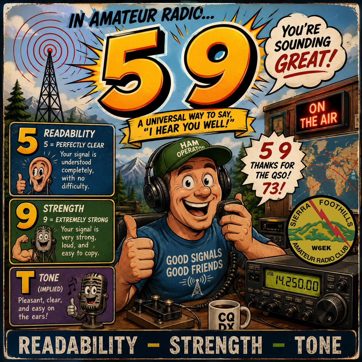
Jay had been concerned that I might not be able to access the grounds until about a half hour before it opened to the public at 4:00pm, but I decided to try at 1:30PM and had no problems. The special parking area for participants was located just below the levy adjacent to the animal barn, with Building C being just next to that – not too far for me to walk with my cane. Another concern was whether they would allow a backpack with electronics taken inside, but there was no check. My parking stub and Fair participant ticket were sufficient to be let in without any questions. I was able to pack my Kenwood HT, spare battery, coax adapters and some miscellaneous items including a bunch of SFARC stickers and a patch in my backpack and walked right into Building C. Nobody was in the booth and the building was very quiet, so I just set up, connected the HT to the external antenna and started calling CQ using the special call station ID K6C. I started out on the standard POTA frequency, but after a couple contacts there with no follow-up I decided to just hop around the repeaters I have programmed into the rig. I made contacts all over the area on 2 meters including Fair Oaks, Carmichael, Citrus Heights, Roseville, Elk Grove, West Sacramento, EL Dorado Hills, and Folsom. At one point I made contact with NZ6Q, John Litz, who is the ARRL Pacific Division Director. It turned out he was driving up to the event and was between Stockton and Lodi. I had 5-9 signals on all contacts, and all contacts reported my signal as being very strong. I was using the 2-watt setting on the rig – not even using full power. Congratulations go to the team led by Jay earlier in the previous week who had set up the rooftop antenna as it had excellent coverage. At about 3:30, Dr. Carol Millazo (KP4MD) (our ARRL Pacific Division Vice Director) arrived, and John Litz arrived shortly after. Another ham who I didn’t get the name of also was present that day in the booth; he was an area ARES volunteer. As my operating time ended at 4:00, I switched to greeting the public. It took a while for the public at large to start filtering into the building, but we eventually did have several families with young children who stopped by and asked a lot of questions. John was especially helpful at engaging them in conversation. We had several fact sheets they could take home, among them a list of the local clubs in the area that I had printed up. One fun activity was a Morse code key and oscillator set up with a sheet that showed the code for each letter; the kids were encouraged to write out their first names in code and then use the key to send it. This proved quite a popular activity and got them engaged. It was an honor to work the booth with two of the ARRL representatives for our area.
Although I did not see him on the day I was there, a friend of mine, Bill Shocknesse (N6NA), was apparently there at the beginning of the Fair and was communicating with the satellite. Our own club’s recently joined young member Maxim had been there on the first weekend and apparently made several contacts on 40 meters.
I had a good time operating and greeting the public, and will try to participate again next year. I encourage more of our club members to come out and participate as well.

 Ask your kids or grandkids what their favorite radio station is and who their favorite DJ is. Among ages 13–24, over-the-air radio accounts for roughly 16% of total audio time. Only 10% of ages 13–17 and 5% of ages 18–24 identify AM/FM as their primary source for discovering music (from Radio World and Radio Ink).
 According to Edison Research, AM radio is in a substantially weaker position with people under 25 than FM radio. Current national studies generally combine AM and FM, so there is no credible published percentage showing how many under-25s can name an AM station. AM isn’t dead as a distribution system, but among younger listeners it has a serious brand awareness and intentional-use problem that makes ad monetization challenging beyond radio’s broader challenge. Large antenna systems and towers require substantial land, ground radials, and specialized maintenance, which makes AM cost prohibitive in many markets. A National Alliance of State Broadcasters Associations survey of more than 1,000 AM stations found that over 70% of AM radio stations on the air today have an FM simulcast.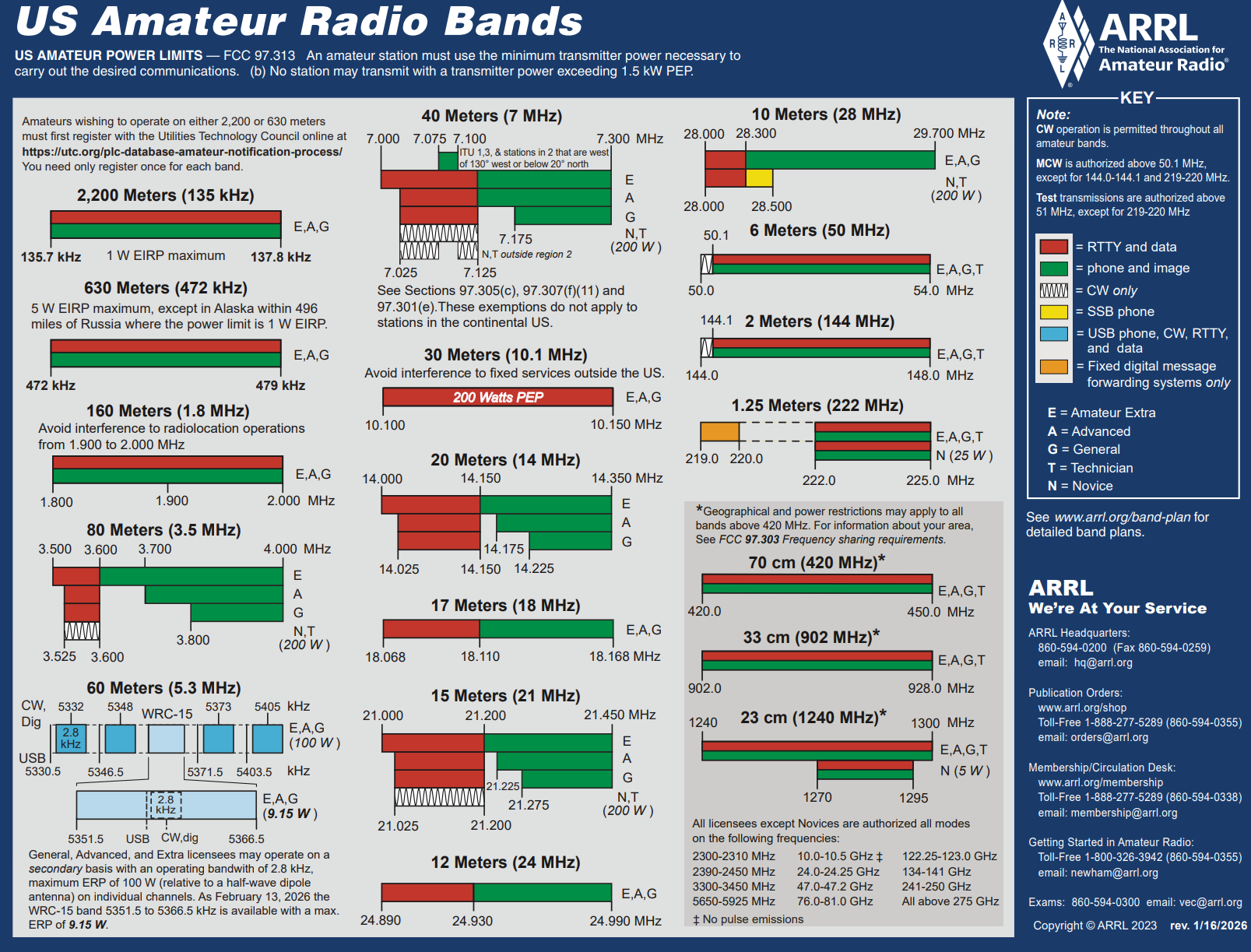
 Interference occurs when unwanted radio-frequency signals disrupt the use of your television, radio, or cordless telephone. Interference may prevent reception altogether, cause only a temporary loss of signal, or affect the quality of the sound or picture produced by your equipment.