
INTERACTIVE BAND PLAN
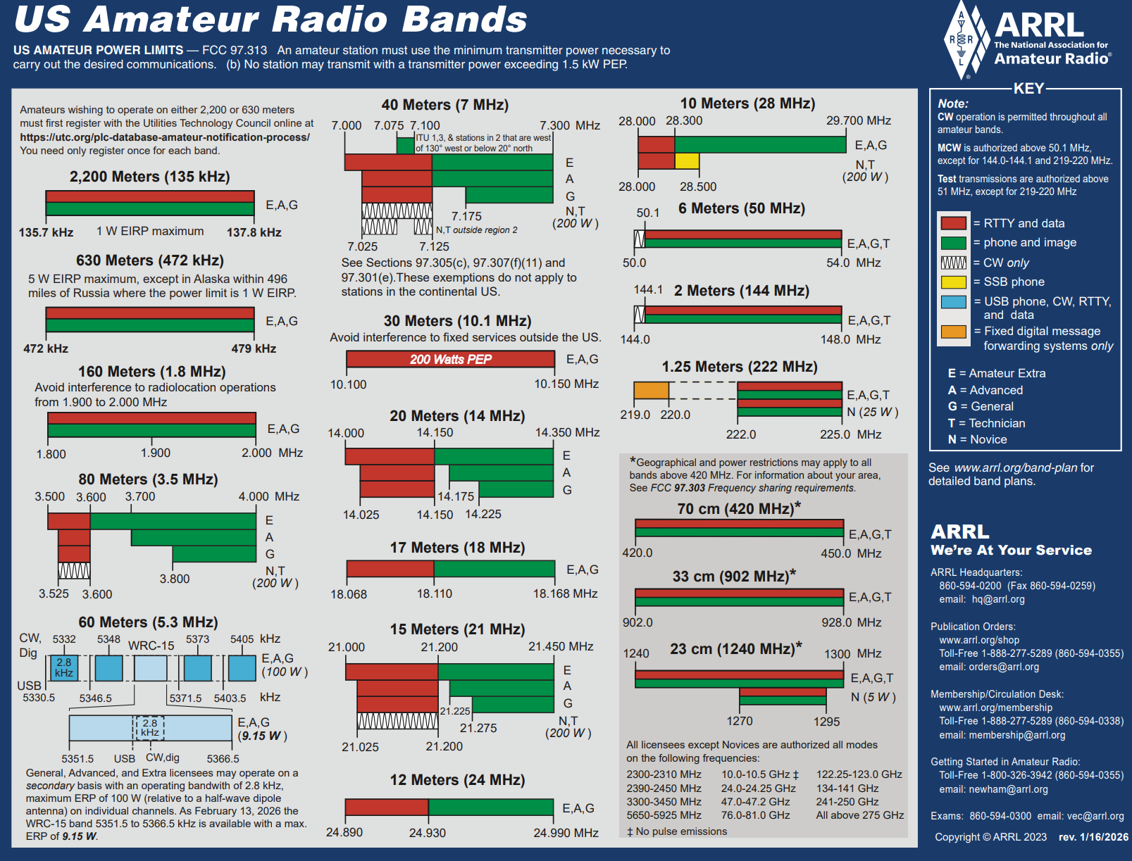
 The ARRL band plan is a PDF you squint at, scroll through, and eventually give up on. The following is the same information made usable and interactive.
Search a frequency or a mode and jump straight to it. Filter by license class to see exactly where your privileges begin and end. Every segment is color-coded by mode, so you can tell at a glance whether you’re about to call CQ in the middle of the digital watering hole.
Covers 2200 meters through microwave. Works on your phone in the field, on your laptop at the operating desk, and in color-blind-friendly and light modes.
A band plan is a voluntary agreement among operators to keep incompatible modes out of each other’s way. It is not the law, Part 97 is. Always check current FCC rules before transmitting.
SFARC SPECTRUM EXPLORER
A band plan is a voluntary division of a band to avoid interference between incompatible modes.
- CW
- Phone / SSB / AM
- Digital / Data
- FM / Repeater
- Beacons
- Satellite / EME
- ATV / SSTV
- Experimental
- Other / Shared
| Frequency | Use |
|---|---|
| 135.7 - 137.8 kHz | 1 W EIRP maximum |
| 472 - 479 kHz | 5 W EIRP maximum Except in Alaska within 496 miles of Russia where the power limit is 1 W EIRP. |
- General, Advanced and Amateur Extra class licensees are authorized to use these bands.
- Amateurs wishing to operate on either 2,200 or 630 meters must first register with the Utilities Technology Council online at https://utc.org/plc-database-amateur-notification-process/. You need only register once for each band.
| Frequency | Use |
|---|---|
| 1.800 - 2.000 | CW |
| 1.800 - 1.810 | Digital Modes |
| 1.810 | CW QRP |
| 1.843 - 2.000 | SSB, SSTV and other wideband modes |
| 1.910 | SSB QRP |
| 1.995 - 2.000 | Experimental |
| 1.999 - 2.000 | Beacons |
| Frequency | Use |
|---|---|
| 3.590 | RTTY/Data DX |
| 3.570 - 3.600 | RTTY/Data |
| 3.790 - 3.800 | DX window |
| 3.845 | SSTV |
| 3.885 | AM calling frequency |
| Frequency | Use |
|---|---|
| 5330.5 kHz | USB phone¹ and CW/RTTY/data² |
| 5346.5 kHz | USB phone¹ and CW/RTTY/data² |
| 5351.5 - 5366.5 kHz | USB phone¹ and CW/RTTY/data 9.15 watts ERP maximum |
| 5371.5 kHz | USB phone¹ and CW/RTTY/data² |
| 5403.5 kHz | USB phone¹ and CW/RTTY/data² |
- Only one signal at a time is permitted on individual frequencies (channels). The center frequency range 5351.5-5366.5 kHz will only support multiple QRP users.
- Maximum effective radiated output is 100 W PEP (except 9.15 watts ERP for the center range of frequencies 5351.5-5366.5 kHz).
- ¹ USB is limited to 2.8 kHz bandwidth.
- ² CW and digital emissions must be centered 1.5 kHz above the channel frequencies indicated in the chart.
| Frequency | Use |
|---|---|
| 7.040 | RTTY/Data DX |
| 7.080 - 7.125 | RTTY/Data |
| 7.171 | SSTV |
| 7.290 | AM calling frequency |
| Frequency | Use |
|---|---|
| 10.130 - 10.140 | RTTY |
| 10.140 - 10.150 | Packet |
| Frequency | Use |
|---|---|
| 14.070 - 14.095 | RTTY |
| 14.095 - 14.0995 | Packet |
| 14.100 | NCDXF Beacons |
| 14.1005 - 14.112 | Packet |
| 14.230 | SSTV |
| 14.286 | AM calling frequency |
| Frequency | Use |
|---|---|
| 18.100 - 18.105 | RTTY |
| 18.105 - 18.110 | Packet |
| Frequency | Use |
|---|---|
| 21.070 - 21.110 | RTTY/Data |
| 21.340 | SSTV |
| Frequency | Use |
|---|---|
| 24.920 - 24.925 | RTTY |
| 24.925 - 24.930 | Packet |
| Frequency | Use |
|---|---|
| 28.000 - 28.070 | CW |
| 28.070 - 28.150 | RTTY |
| 28.150 - 28.190 | CW |
| 28.200 - 28.300 | Beacons |
| 28.300 - 29.300 | Phone |
| 28.680 | SSTV |
| 29.000 - 29.200 | AM |
| 29.300 - 29.510 | Satellite Uplinks or Downlinks |
| 29.520 - 29.590 | Repeater Inputs |
| 29.600 | FM Simplex |
| 29.610 - 29.700 | Repeater Outputs |
| Frequency | Use |
|---|---|
| 50.0 - 50.1 | CW, beacons |
| 50.060 - 50.080 | beacon subband |
| 50.1 - 50.3 | SSB, CW |
| 50.10 - 50.125 | DX window |
| 50.125 | SSB calling |
| 50.3 - 50.6 | All modes |
| 50.6 - 50.8 | Nonvoice communications |
| 50.62 | Digital (packet) calling |
| 50.8 - 51.0 | Radio remote control (20-kHz channels) |
| 51.0 - 51.1 | Pacific DX window |
| 51.12 - 51.48 | Repeater inputs (19 channels) |
| 51.12 - 51.18 | Digital repeater inputs |
| 51.5 - 51.6 | Simplex (six channels) |
| 51.62 - 51.98 | Repeater outputs (19 channels) |
| 51.62 - 51.68 | Digital repeater outputs |
| 52.0 - 52.48 | Repeater inputs (except as noted; 23 channels) |
| 52.02, 52.04 | FM simplex |
| 52.2 | TEST PAIR (input) |
| 52.5 - 52.98 | Repeater output (except as noted; 23 channels) |
| 52.525 | Primary FM simplex |
| 52.54 | Secondary FM simplex |
| 52.7 | TEST PAIR (output) |
| 53.0 - 53.48 | Repeater inputs (except as noted; 19 channels) |
| 53.0 | Remote base FM simplex |
| 53.02 | Simplex |
| 53.1, 53.2, 53.3, 53.4 | Radio remote control |
| 53.5 - 53.98 | Repeater outputs (except as noted; 19 channels) |
| 53.5, 53.6, 53.7, 53.8 | Radio remote control |
| 53.52, 53.9 | Simplex |
| Frequency | Use |
|---|---|
| 144.00 - 144.05 | EME (CW) |
| 144.05 - 144.10 | General CW and weak signals |
| 144.10 - 144.20 | EME and weak-signal SSB |
| 144.200 | National calling frequency |
| 144.200 - 144.275 | General SSB operation |
| 144.275 - 144.300 | Propagation beacons |
| 144.30 - 144.50 | New OSCAR subband |
| 144.50 - 144.60 | Linear translator inputs |
| 144.60 - 144.90 | FM repeater inputs |
| 144.90 - 145.10 | Weak signal and FM simplex 145.01, 03, 05, 07, 09 are widely used for packet |
| 145.10 - 145.20 | Linear translator outputs |
| 145.20 - 145.50 | FM repeater outputs |
| 145.50 - 145.80 | Miscellaneous and experimental modes |
| 145.80 - 146.00 | OSCAR subband |
| 146.01 - 146.37 | Repeater inputs |
| 146.40 - 146.58 | Simplex |
| 146.52 | National Simplex Calling Frequency |
| 146.61 - 146.97 | Repeater outputs |
| 147.00 - 147.39 | Repeater outputs |
| 147.42 - 147.57 | Simplex |
| 147.60 - 147.99 | Repeater inputs |
- The frequency 146.40 MHz is used in some areas as a repeater input.
- This band plan has been proposed by the ARRL VHF-UHF Advisory Committee.
| Frequency | Use |
|---|---|
| 222.0 - 222.150 | Weak-signal modes |
| 222.0 - 222.025 | EME |
| 222.05 - 222.06 | Propagation beacons |
| 222.1 | SSB & CW calling frequency |
| 222.10 - 222.15 | Weak-signal CW & SSB |
| 222.15 - 222.25 | Local coordinator's option; weak signal, ACSB, repeater inputs, control |
| 222.25 - 223.38 | FM repeater inputs only |
| 223.40 - 223.52 | FM simplex |
| 223.52 - 223.64 | Digital, packet |
| 223.64 - 223.70 | Links, control |
| 223.71 - 223.85 | Local coordinator's option; FM simplex, packet, repeater outputs |
| 223.85 - 224.98 | Repeater outputs only |
- The 222 MHz band plan was adopted by the ARRL Board of Directors in July 1991.
| Frequency | Use |
|---|---|
| 420.00 - 426.00 | ATV repeater or simplex with 421.25 MHz video carrier control links and experimental |
| 426.00 - 432.00 | ATV simplex with 427.250-MHz video carrier frequency |
| 432.00 - 432.07 | EME (Earth-Moon-Earth) |
| 432.07 - 432.10 | Weak-signal CW |
| 432.10 | 70-cm calling frequency |
| 432.10 - 432.30 | Mixed-mode and weak-signal work |
| 432.30 - 432.40 | Propagation beacons |
| 432.40 - 433.00 | Mixed-mode and weak-signal work |
| 433.00 - 435.00 | Auxiliary/repeater links |
| 435.00 - 438.00 | Satellite only (internationally) |
| 438.00 - 444.00 | ATV repeater input with 439.250-MHz video carrier frequency and repeater links |
| 442.00 - 445.00 | Repeater inputs and outputs (local option) |
| 445.00 - 447.00 | Shared by auxiliary and control links, repeaters and simplex (local option) |
| 446.00 | National simplex frequency |
| 447.00 - 450.00 | Repeater inputs and outputs (local option) |
| Frequency | Use |
|---|---|
| 902.000 - 902.075 | FM / other incl. DV (repeater inputs, 25 MHz split paired with 927.000-927.075) or CW/SSB weak signal 12.5 kHz channel spacing (Note 2) |
| 902.075 - 902.100 | CW/SSB - Weak signal |
| 902.100 | CW/SSB - Weak signal calling Regional option |
| 902.100 - 902.125 | CW/SSB - Weak signal |
| 902.125 - 903.000 | FM/other incl. DV - Repeater inputs, 25 MHz split paired with 927.1250-928.0000 12.5 kHz channel spacing |
| 903.000 - 903.100 | CW/SSB - Beacons and weak signal |
| 903.100 | CW/SSB - Weak signal calling Regional option |
| 903.100 - 903.400 | CW/SSB - Weak signal |
| 903.400 - 909.000 | Mixed modes - Mixed operations including control links |
| 909.000 - 915.000 | Analog/digital - Broadband multimedia (ATV, DATV, SS) Notes 3, 4 |
| 915.000 - 921.000 | Analog/digital - Broadband multimedia (ATV, DATV, SS) Notes 3, 4 |
| 921.000 - 927.000 | Analog/digital - Broadband multimedia (ATV, DATV, SS) Notes 3, 4 |
| 927.000 - 927.075 | FM / other incl. DV - Repeater outputs, 25 MHz split paired with 902.0000-902.0750 12.5 kHz channel spacing |
| 927.075 - 927.125 | FM / other incl. DV - Simplex |
| 927.125 - 928.000 | FM / other incl. DV - Repeater outputs, 25 MHz split paired with 902.125-903.000 12.5 kHz channel spacing (Notes 5, 6) |
- 1) Significant regional variations in band utilization and noise sources preclude one plan suitable for all parts of the country. Locally coordinated plans always take precedence over national recommendations.
- 2) May be used for either repeater inputs or weak-signal as regional needs dictate.
- 3) Division into channels and/or separation of uses within these segments may be done regionally based on needs and usage, such as for 2 MHz-wide digital TV.
- 4) These segments may also be designated regionally to accommodate alternative repeater splits.
- 5) Simplex FM calling frequency 927.500 or regionally selected alternative.
- 6) Additional FM simplex frequencies may be designated regionally.
| Frequency | Use |
|---|---|
| 1240.000 - 1246.000 | ATV - ATV Channel #1 |
| 1246.000 - 1248.000 | FM, digital - Point-to-point links paired with 1258.000-1260.000 |
| 1248.000 - 1252.000 | Digital |
| 1252.000 - 1258.000 | ATV - ATV Channel #2 |
| 1258.000 - 1260.000 | FM, digital - Point-to-point links paired with 1246.000-1248.000 |
| 1240.000 - 1260.000 | FM ATV - Regional option |
| 1260.000 - 1270.000 | Various - Satellite uplinks, Experimental, Simplex ATV |
| 1270.000 - 1276.000 | FM, digital - Repeater inputs, 25 kHz spacing, paired with 1282.000-1288.000 |
| 1270.000 - 1274.000 | FM, digital - Repeater inputs, 25 kHz spacing, paired with 1290.000-1294.000 (Regional option) |
| 1276.000 - 1282.000 | ATV - ATV Channel #3 |
| 1282.000 - 1288.000 | FM, digital - Repeater outputs, 25 kHz spacing, paired with 1270.000-1276.000 |
| 1288.000 - 1294.000 | Various - Broadband Experimental, Simplex ATV |
| 1290.000 - 1294.000 | FM, digital - Repeater outputs, 25 kHz spacing, paired with 1270.000-1274.000 (Regional option) |
| 1294.000 - 1295.000 | FM - FM simplex |
| 1294.500 | FM - National FM simplex calling frequency |
| 1295.000 - 1297.000 | Narrow Band Segment |
| 1295.000 - 1295.800 | Various - Narrow Band Image, Experimental |
| 1295.800 - 1296.080 | CW, SSB, digital - EME |
| 1296.080 - 1296.200 | CW, SSB - Weak Signal |
| 1296.100 | CW, SSB - CW, SSB calling frequency |
| 1296.200 - 1296.400 | CW, digital - Beacons |
| 1296.400 - 1297.000 | Various - General Narrow Band |
| 1297.000 - 1300.000 | Digital |
- The need to avoid harmful interference to FAA radars may limit amateur use of certain frequencies in the vicinity of the radars.
| Frequency | Use |
|---|---|
| 2300.000 - 2303.000 | Analog & Digital, incl. full duplex; paired with 2390-2393 0.05 - 1.0 MHz |
| 2303.000 - 2303.750 | Analog & Digital; paired with 2393-2393.750 < 50 kHz |
| 2303.75 - 2304.000 | SSB, CW, digital weak-signal |
| 2304.000 - 2304.100 | Weak Signal EME Band 3 kHz or less |
| 2304.10 - 2304.300 | SSB, CW, digital weak-signal (Note 1) 3 kHz or less |
| 2304.300 - 2304.400 | Beacons 3 kHz or less |
| 2304.400 - 2304.750 | SSB, CW, digital weak-signal & NBFM 6 kHz or less |
| 2304.750 - 2305.000 | Analog & Digital; paired with 2394.750-2395 < 50 kHz |
| 2305.000 - 2310.000 | Analog & Digital; paired with 2395-2400 (Note 2) 0.05 - 1.0 MHz |
| 2310.000 - 2390.000 | NON-AMATEUR |
| 2390.000 - 2393.000 | Analog & Digital, incl. full duplex; paired with 2300-2303 0.05 - 1.0 MHz |
| 2393.000 - 2393.750 | Analog & Digital; paired with 2303-2303.750 < 50 kHz |
| 2393.750 - 2394.750 | Experimental |
| 2394.750 - 2395.000 | Analog & Digital; paired with 2304.750-2305 < 50 kHz |
| 2395.000 - 2400.000 | Analog & Digital, incl. full duplex; paired with 2305-2310 0.05 - 1.0 MHz |
| 2400.000 - 2410.000 | Amateur Satellite Communications 6 kHz or less |
| 2410.000 - 2450.000 | Broadband Modes (Notes 3, 4) 22 MHz max. |
- 1: 2304.100 is the National Weak-Signal Calling Frequency.
- 2: 2305-2310 is allocated on a primary basis to Wireless Communications Services (Part 27). Amateur operations in this segment, which are secondary, may not be possible in all areas.
- 3: Broadband segment may be used for any combination of high-speed data (e.g. 802.11 protocols), Amateur Television and other high-bandwidth activities. Division into channels may be done regionally.
- 4: 2424.100 is the Japanese EME transmit frequency.
- These band plans were adopted by the ARRL Board of Directors in 2012.
| Frequency | Use |
|---|---|
| 3300.000 - 3309.000 | Analog & Digital, incl. Full Duplex; paired with 3430.0-3439.0; 130 MHz Split 0.1 - 1.0 MHz |
| 3309.000 - 3310.000 | Experimental |
| 3310.000 - 3330.000 | Analog & Digital, incl. Full Duplex; paired with 3410.0-3430.0; 100 MHz Split > 1.0 MHz |
| 3330.000 - 3332.000 | Experimental |
| 3332.000 - 3339.000 | RADIO ASTRONOMY PROTECTED BAND (Note 4) |
| 3339.000 - 3345.800 | Analog & Digital, incl. Full Duplex; paired with 3439.0-3445.8; 100 MHz Split 0.1 - 1.0 MHz |
| 3345.800 - 3352.500 | RADIO ASTRONOMY PROTECTED BAND (Note 4) |
| 3352.500 - 3355.000 | Analog & Digital, incl. Full Duplex; paired with 3452.5-3455.0; 100 MHz Split 0.05 - 0.2 MHz |
| 3355.000 - 3357.000 | Experimental |
| 3357.000 - 3360.000 | Analog & Digital, incl. Full Duplex; paired with 3457.0-3460.0 50 kHz or less |
| 3360.000 - 3400.000 | OFDM, others - Broadband Modes (Note 3) 22 MHz max. |
| 3360.000 - 3380.000 | ATV - Amateur Television of all authorized modulation standards/formats at local option |
| 3400.000 - 3410.000 | CW, SSB, NBFM - Amateur Satellite Communications 6 kHz or less |
| 3400.000 - 3400.300 | CW, SSB, Digital - Weak Signal EME Band 3 kHz or less |
| 3400.300 - 3401.000 | CW, SSB, Digital - Terrestrial Weak Signal Band - Future (Note 2) 3 kHz or less |
| 3400.100 | CW, SSB, Digital - EME Calling Frequency |
| 3410.000 - 3430.000 | Analog & Digital, incl. Full Duplex; paired with 3310.0-3330.0; 100 MHz Split > 1.0 MHz |
| 3430.000 - 3439.000 | Analog & Digital, incl. Full Duplex; paired with 3300.0-3309.0; 130 MHz Split 0.1 - 1.0 MHz |
| 3439.000 - 3445.800 | Analog & Digital, incl. Full Duplex; paired with 3339.0-3345.8; 100 MHz Split 0.1 - 1.0 MHz |
| 3445.800 - 3450.000 | Experimental |
- FCC announced that all Amateur Radio use of the band 3.45 - 3.5 GHz must cease effective April 14, 2022. See http://www.arrl.org/3-ghz-band for detailed history.
- Note 1 - Includes all other emission modes authorized in the 9 cm band whose necessary bandwidth does not exceed the suggested bandwidths listed.
- Note 2 - Weak Signal Terrestrial legacy users are encouraged to move to 3400.3 to 3401.0 MHz as time and resources permit.
- Note 3 - Broadband segments may be used for any combination of high-speed data (e.g. 802.11 protocols), Amateur Television and other high-bandwidth activities. Division into channels may be done regionally.
- Note 4 - Per ITU RR 5.149 from WRC-07, these band segments are also used for Radio Astronomy. Amateur use should be first coordinated with the National Science Foundation (esm@nsf.gov).
| Frequency | Use |
|---|---|
| 5650.0 - 5670.0 | Amateur Satellite; Up-Link Only |
| 5650.0 - 5675.0 | Experimental 0.05 - 1.0 MHz |
| 5675.0 - 5750.0 | Analog & Digital; paired with 5850-5925 MHz (Note 2) >= 1.0 MHz |
| 5750.0 - 5756.0 | Analog & Digital; paired with 5820-5826 MHz >= 25 kHz and < 1 MHz |
| 5756.0 - 5759.0 | Analog & Digital; paired with 5826-5829 MHz <= 50 kHz |
| 5759.0 - 5760.0 | SSB, CW, Digital Weak-Signal < 6 kHz |
| 5760.0 - 5760.1 | EME < 3 kHz |
| 5760.1 - 5760.3 | SSB, CW, Digital Weak-Signal (Note 1) < 6 kHz |
| 5760.3 - 5760.4 | Beacons < 3 kHz |
| 5760.4 - 5761.0 | SSB, CW, Digital Weak-Signal < 6 kHz |
| 5761.0 - 5775.0 | Experimental <= 50 kHz |
| 5775.0 - 5800.0 | Experimental >= 100 kHz |
| 5800.0 - 5820.0 | Experimental |
| 5820.0 - 5826.0 | Analog & Digital; paired with 5750-5756 MHz >= 25 kHz and < 1 MHz |
| 5826.0 - 5829.0 | Analog & Digital; paired with 5756-5759 MHz <= 50 kHz |
| 5829.0 - 5850.0 | Experimental 0.05 - 1.0 MHz |
| 5830.0 - 5850.0 | Amateur Satellite; Down-Link Only |
| 5850.0 - 5925.0 | Analog & Digital; paired with 5675-5750 MHz (Note 2) >= 1.0 MHz |
- Note 1: 5760.1 is the National Weak-Signal Calling Frequency.
- Note 2: Broadband segment may be used for any combination of high-speed data (e.g. 802.11 protocols), Amateur Television and other high-bandwidth activities. Division into channels may be done regionally.
| Frequency | Use |
|---|---|
| 10000.000 - 10050.000 | Experimental |
| 10050.000 - 10100.000 | Analog & Digital; paired with 10300-10350 <= 100 kHz |
| 10100.000 - 10115.000 | Analog & Digital; paired with 10350-10365 >= 25 kHz and < 1 MHz |
| 10115.000 - 10117.000 | Analog & Digital; paired with 10365-10367 <= 50 kHz |
| 10117.000 - 10120.000 | Experimental |
| 10120.000 - 10125.000 | Analog & Digital; paired with 10370-10375 <= 50 kHz |
| 10125.000 - 10200.000 | Analog & Digital; paired with 10375-10450 (Note 2) >= 1 MHz |
| 10200.000 - 10300.000 | Wideband Gunnplexers |
| 10300.000 - 10350.000 | Analog & Digital; paired with 10050-10100 <= 100 kHz |
| 10350.000 - 10365.000 | Analog & Digital; paired with 10100-10115 >= 25 kHz and < 1 MHz |
| 10365.000 - 10367.000 | Analog & Digital; paired with 10115-10117 <= 50 kHz |
| 10367.000 - 10368.300 | SSB, CW, Digital Weak-Signal & NBFM (Note 1) 6 kHz or less |
| 10368.300 - 10368.400 | Beacons 6 kHz or less |
| 10368.400 - 10370.000 | SSB, CW, Digital Weak-Signal & NBFM 6 kHz or less |
| 10370.000 - 10375.000 | Analog & Digital; paired with 10120-10125 <= 50 kHz |
| 10375.000 - 10450.000 | Analog & Digital; paired with 10125-10200 (Note 2) >= 1 MHz |
| 10450.000 - 10500.000 | Space, Earth & Telecommand Stations |
- Note 1: 10368.100 is the National Weak-Signal Calling Frequency.
- Note 2: Broadband segment may be used for any combination of high-speed data (e.g. 802.11 protocols), Amateur Television and other high-bandwidth activities. Division into channels may be done regionally.
| Frequency | Use |
|---|---|
| Above 10.5 GHz | All modes and licensees (except Novices) are authorized. |
- US amateurs must check Sections 97.301, 97.303, 97.305 and 97.307 for sharing requirements before operating.
No band, frequency, or mode matches that search.
 Interference occurs when unwanted radio-frequency signals disrupt the use of your television, radio, or cordless telephone. Interference may prevent reception altogether, cause only a temporary loss of signal, or affect the quality of the sound or picture produced by your equipment.